59.5 x 40 x 41.5
Wood, glass, metal and ivory
CAT. 1878 : 112
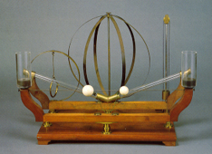
Apparelho para mostrar os effeitos da força centrifuga (Salleron).
Apparatus used to show the effects of centrifugal forces (Salleron).
This apparatus shows the effects of rotating movement on various solid and liquid bodies. It consists of a wooden base with a crank attached to a notched wheel, which is connected by a chain to another, smaller, notched wheel. Various accessories may be easily applied to the axle of the latter wheel, each of which is intended to illustrate specific aspects associated with systems with rotational movement.
The apparatus was built by J. Salleron, Paris, in 1875 and is complete. The accessories are shown schematically in the diagrams below. Some of these accessories look similar to those invented earlier, namely instruments like those described in Physices Elementa by ´s Gravesande, and were intended to be used on "a machine for the study of central forces". One of these types of machines existed in the Gabinete de Física of the eighteenth century (inventoried in the INDEX 1788 with the number I.II.p.193) and must have been one of the most complex and versatile existing pieces.
Described below are each of the components of this assemblage, together with the effects which can be studied. These effects will be explained here relative to the rotational frame, resorting consequently to forces of inertia, in this case centrifugal forces. In a referential frame with angular speed w, a body with a mass m, and at a distance r from the rotation axle, is subject to a centrifugal force of intensity F = mw2 r.
The components of the assemblage are illustrated in figures A to G, respectively.
A. Wooden base to which the various accessories may be attached.
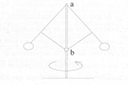
B. The two brass spheres of this accessory are joined to two articulated beams. Point a is fixed, and ring b moves along the vertical axle. When the system turns with an angular speed w the spheres rise until reaching a position of equilibrium where, for each of them, the centrifugal force equals the horizontal component of force of constraint,coming from the metallic beam. The vertical components of these forces balance the weight of the spheres.
This device was used with steam powered machines, to automatically regulate the opening of valves and at the same time control the flow of vapour as a function of the speed of rotation of the machine. It is known as Watt's regulator, in honour of its inventor.
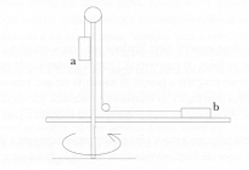
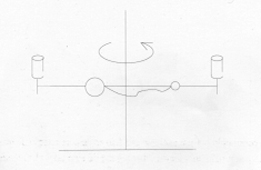
C. This device consists of two brass cylinders attached by an inextensible string, which goes through two pulleys, in a way which allows one to slide in a vertical direction and the other in a horizontal direction. When not rotating, the cylinder a is set on the base. When the assemblage is subject to rotation around the vertical axle, the two cylinders move to a new balanced position which is reached when the weight of the suspended cylinder and the centrifugal force to which cylinder b is subject are equal. This accessory is similar to an instrument from the 18th century, (instrument 59).
D. This accessory is composed of two spheres of different mass, joined by a string, which can move freely along a horizontal metallic spindle. Depending on the initial position of both spheres, they move to one or to the other side of the axle when the assemblage acquires rotational speed. Still, if we choose the initial position correctly, it is possible to reach equilibrium (at which each sphere is positioned at each of the sides of the rotational axle, as seen in the picture) which is independent of the rotational speed. Under these conditions, the string remains stretched, and the intensity of the centrifugal forces that act in each of the spheres are equal. The ratio between the distances of each of the spheres to the rotational axle is equal to the inverse of the quotient between the respective masses.
Another part of this accessory is a pair of cups, situated at each of the extremities, probably intended for the observation of the effect of rotation on liquids.
E. A liquid is placed in each of the slanting tubes of this accessory. A small cork sphere can also be placed in the tubes (the sphere can be made of other light material) and another made of lead (or other material denser than the liquid). When the system describes a rotating motion, the liquids move up tothe top of each tube, the same happening with the lead sphere. The cork sphere will move in the same way along the tube. Still, because it is less dense than the liquid, it will occupy a lower position, under the liquid, contrary to that when the system is not in motion. This device thus exemplifies the principle of working of a centrifugal machine.
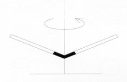
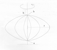
F. This accessory is composed of various steel blades fixed at points a and b, assuming a spherical shape as a whole. Point a is fixed to the vertical axle. Point b consists of a small ring which can slide freely along the axle. When the system is put in rotation one observes that ring descends and its spherical shape turns ellipsoidal. Here we have a deformable body, whose function is similar to that of instrument 60. The explanation of the effect seen in the rotating system is based on the centrifugal force which causes each point of the ring to turn away from the centre of curvature, provoking its elastic deformation.
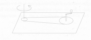
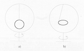
G. This accessory consists of a metal ring which is fixed to a rotating axle to which a smaller ring is fastened, hanging from a wire over the line of the vertical axle. When the system is rotating at a certain angular speed, the ring also turns at the same speed. When the the angular speed is big enough, the small ring begins to incline until it assumes a horizontal position. This surprising result constitutes one of the most interesting demonstrations of this assemblage.
Actually, the system is initially at a position of equilibrium in the rotational frame (position a) in which the tension on the wire and the weight of the ring are balanced. Each point of the ring is subject to a centrifugal force, whose intensity increases with the distance of the points from the rotating axle. However, this is not a stable equilibrium; a small deviation of the wire in relation to the vertical means that the system does not return to the initial position but instead evolves to a new equilibrium, b, where the centrifugal force experienced by each point of the ring is at its maximum value. The tension of the wire approximately balances the weight of the ring. This position of equilibrium is stable. A slight deviation from this position does not cause a breach of the equilibrium, as the object ends up returning to this position of equilibrium.
Carvalho, Rómulo de, História do Gabinete de Física da Universidade de Coimbra, Universidade de Coimbra, Biblioteca Geral, Coimbra, 1978, pp.350-359.
´s Gravesande, Willem Jacob, Physices Elementa, Leiden, 1742, § 567, Tab. XX.